Shop
- PCB Repair
- Products
- Luxury sofa
- Soldering Practice Kit,3 Kits SMD SMT Weldering Skills Training Board(Soldering-All)
Description
Price: $29.76
(as of Dec 05, 2024 22:48:28 UTC – Details)
Product Description
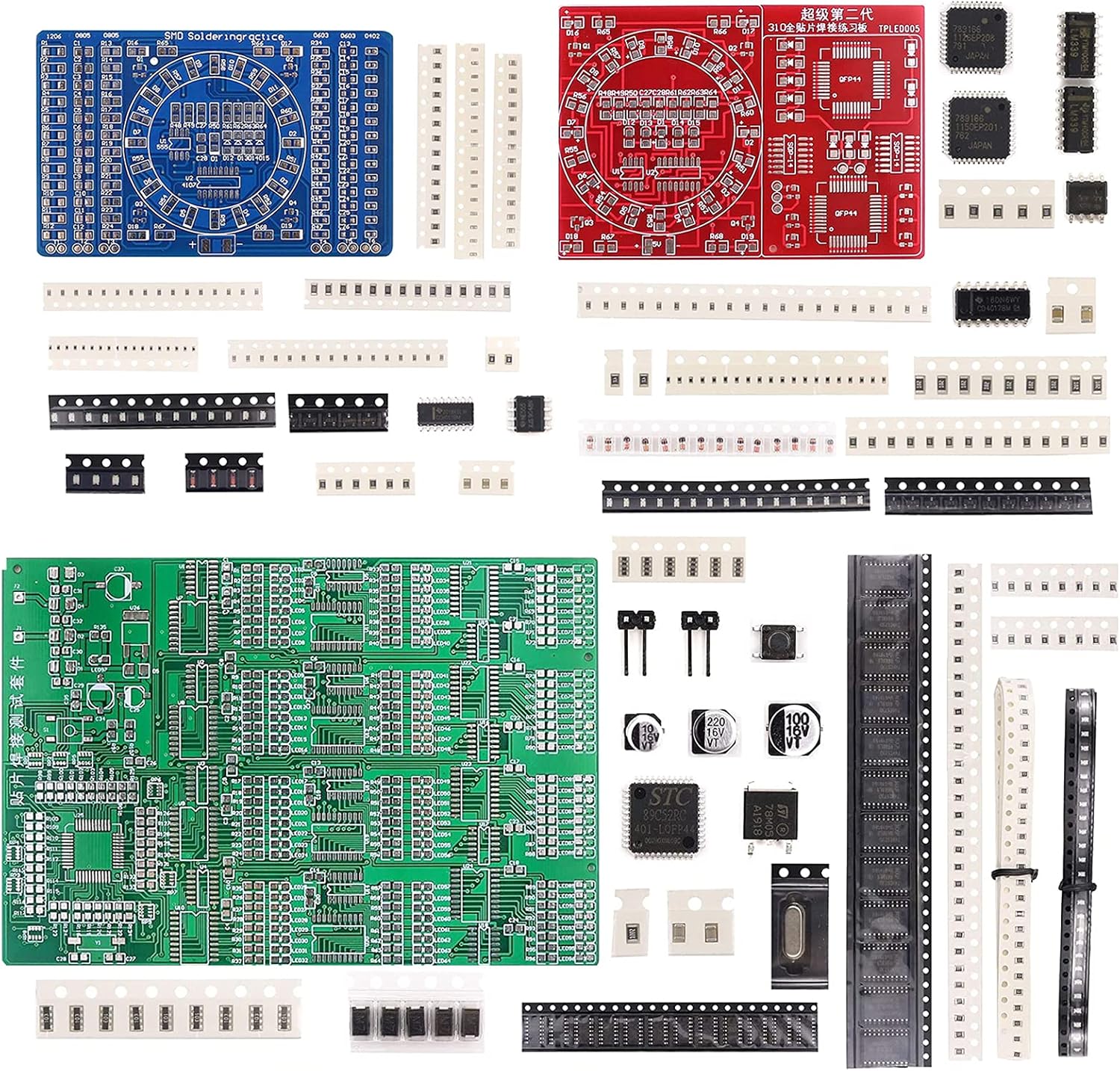
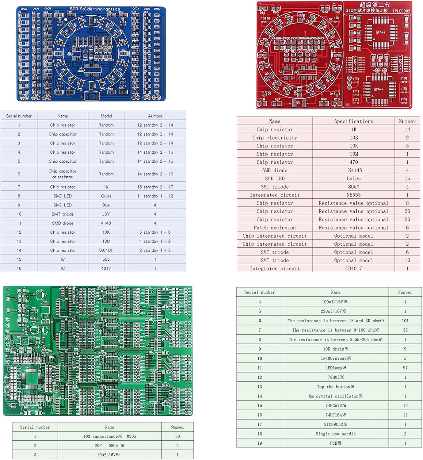
3 kinds of SMD practice kits boards help you improve your soldering skills
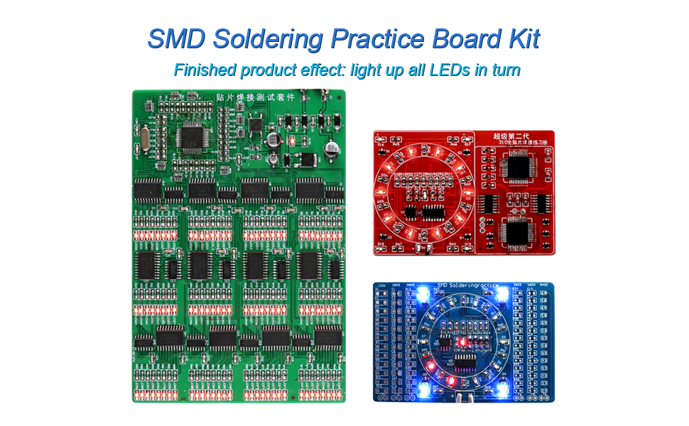

Get 3 sets at a time
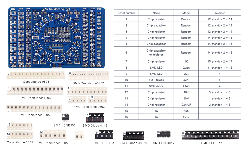

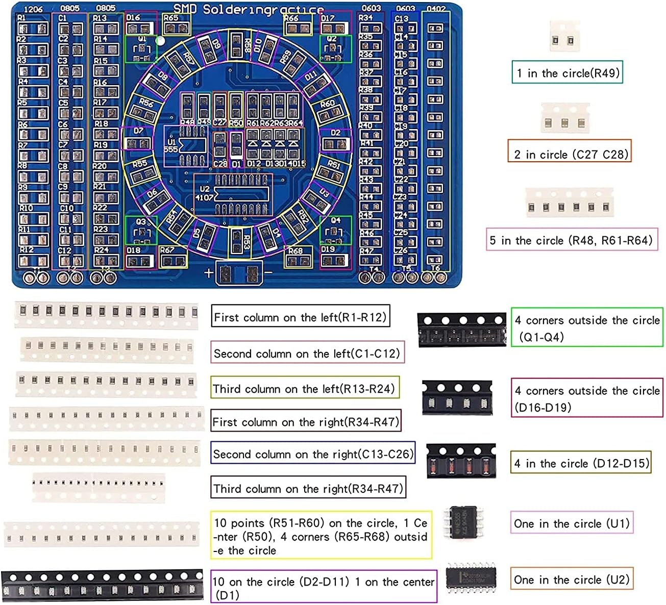
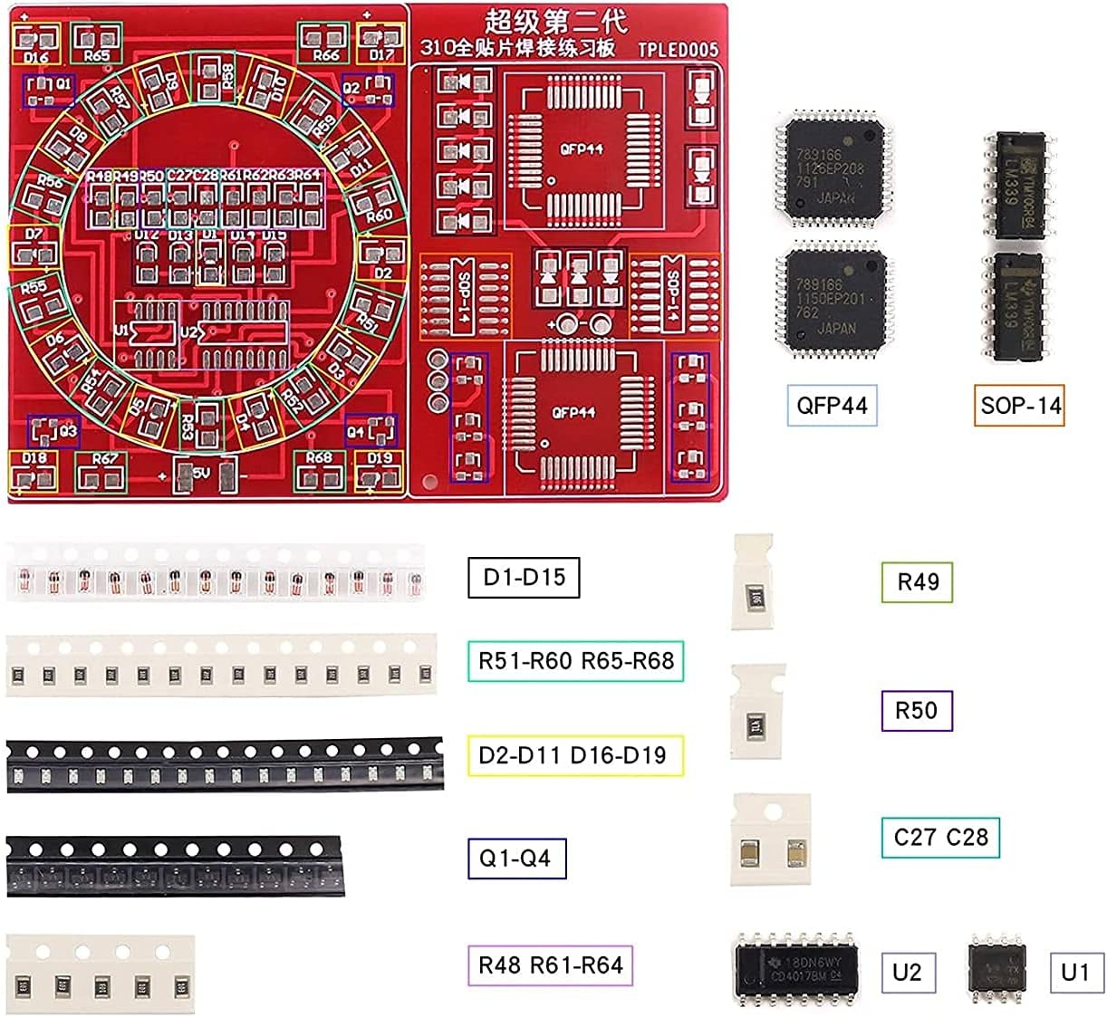
In order to improve the soldering skill level of students majoring in electronics and electronic enthusiasts, referring to the packaging types of SMD components in the electronic product assembly and debugging skills competition of vocational colleges, the SMD soldering practice board is specially designed to improve the soldering level and speed.
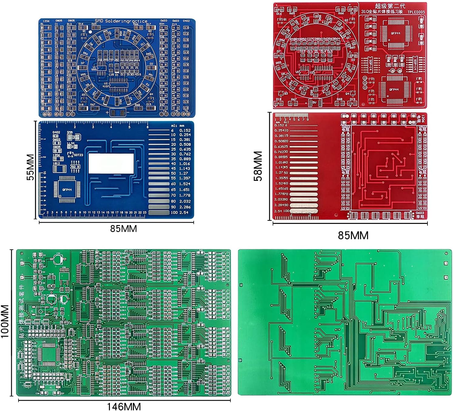
1. Board size: 90 * 60MM
2. Board thickness: 1.6mm
3. Board material: international standard board, all solder pads are tinned, high strength fireproof and fall proof material, which can be disassembled repeatedly.
4. PCB board design is reasonable, the use of SMD components are commonly used.
5. The left and right three columns of components are used to practice soldering, and each column has test points.
6. The circuit in the middle circle is the water lamp circuit, which is composed of CD4017, NE555 and light-emitting diodes. It can work after soldering.
7. The back of the circuit is also used. There is a ruler, which is convenient for measuring components. There are PCB wire examples to facilitate PCB design and use.
8. The working voltage of the circuit is 3 ~ 12V
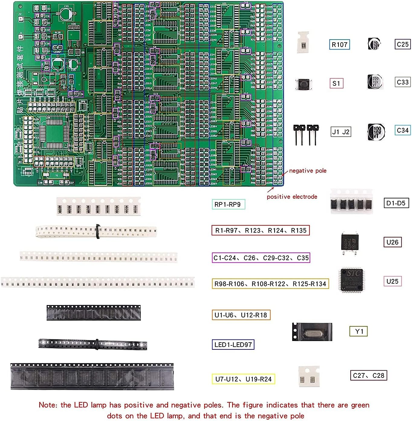
9. This kit contains all the components in the following photos.
Number of components: 125
Number of solder joints: 274
Solder length: 35cm (diameter: 0.6mm)
Sample soldering time: 35 minutes
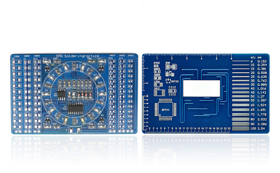

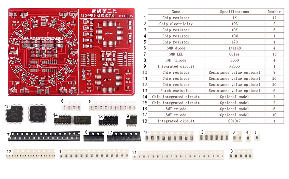

Product description of SMT soldering exercise board Power supply voltage: 5V. The ratio circuit is NE555 + 4017 application circuit, and the multivibrator is composed of NE555. The pulse oscillation signal outputs CD4017 to count through the three pins of NE555. CD4017 will output high level on q0-q4 in turn with the input pulse signal to light up the corresponding light-emitting diodes. These light-emitting diodes are arranged in a circle to form the effect of water lamp. When cd017 counts to 10, the carry end C0 will change from low to high, The driving triode Q1-Q4 is turned on to light up the LED at four corners. When the next pulse comes, the C0 end returns to the low level, and the LED at four corners goes out, and so on.
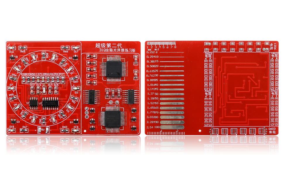

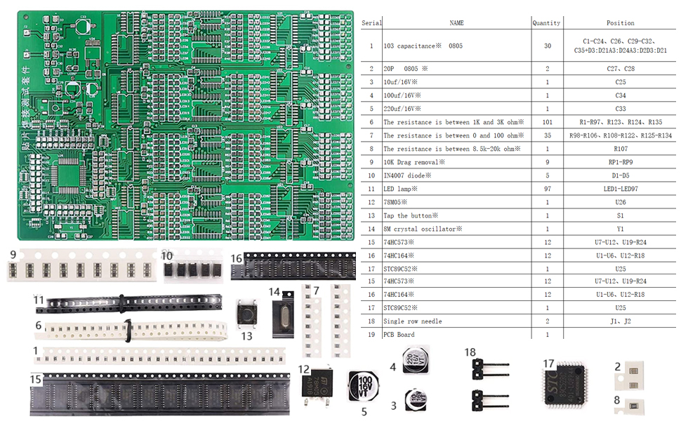

This kit contains 0805 packaged resistor, capacitor, SMD aluminum capacitor, SMD resistor, SMD crystal oscillator, SMD LED lamp, SMD diode, sop14, sop20, tqfp44 and other packaged SMD chips. There are 12 SMD test areas, and the welding difficulty is from low to high. Each group can be tested independently, with short circuit and false soldering test functions, which can judge whether the welding is successful according to the display of LED lamp, There are 12 groups of SMD test areas, which contain 300 SMD welding components in total. Through welding, the welding ability, speed and circuit maintenance ability of various SMD components can be improved to meet the difficulty of the competition. It also has self-test function, and the welding results and welding errors can be seen when the power is on. Principle description:
1. J1 and J2 are the power supply input terminals of the whole chip board, which can work normally when connected with ac6v. When it works normally, all LED lights of the kit can work normally. At first, each group of LED flashes in running water, and then flashes at intervals. Finally, all the LEDs are on, and then flashes. This cycle is used to check whether the LEDs work and whether they are welded well. If the corresponding LED does not flash, it indicates that there is an error or false welding.
2. Ac9v power supply is rectified by D1-D4 diode, and then goes through each filter capacitor to the 1 pin of voltage regulator chip 78m05 (led97 is always on, the rectifier circuit works normally), and outputs DC5V through 3 pins to supply the whole test circuit.
3. The test circuit is controlled by a single chip microcomputer 12 groups of 8-bit LED lamp work. Each group is composed of one 74hc573 and 74HC164. A group can control 8 LEDs, a total of 12 groups. Figure 1 is the control schematic diagram of a group. When it works normally, all the LEDs are on and can flash.
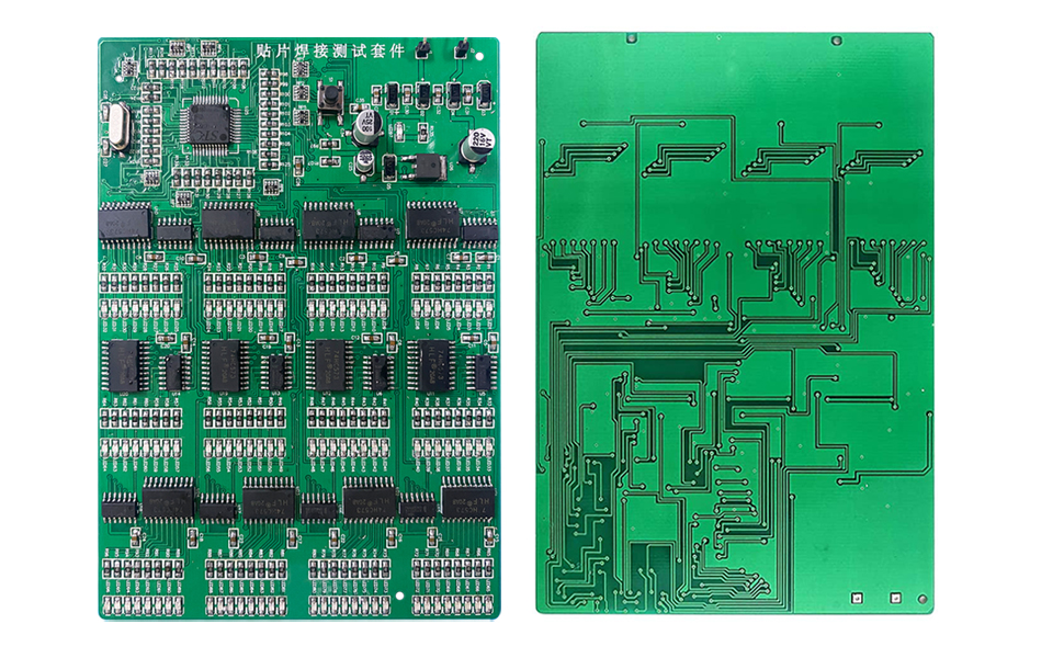

Product name patch welding test kit
PCB material fr-4pcb board
PCB size 146 * 100 mm
The color of the board is green and white
Product weight 62g
Power supply mode DC 9V,Number of solder joints 1079,The number of components is 313.
Applicable to junior welding and mounting personnel The component description adopts common chip components
Data element list,circuit diagram, principle description
✅3 SETS of SUPER VALUE.From easy to difficult SMD components soldering practice kit, high challenge PCB SMD welding skills competition.
✅Professional skills, complete this kit, need a certain professional knowledge base, practical training experience.
✅High quality material, high-quality double-sided spray tin FR-4 circuit board, easy to solder, not easy to oxidize, contribute to success.
✅Technical support, including component list, circuit diagram, principle description and finished product diagram. Please contact us for information.
✅Super quantity components: there are many kinds of components, nearly 20 different kinds of electronic components. There are more than 1400 solder joints and more than 500 components.
Customers say
Customers like the practice value of the product. They mention it’s an excellent skill builder and a really challenging board. However, some customers have reported that the instructions are unreadable and the pictures and instructions sent were blurry. Opinions are mixed on the board quality.
AI-generated from the text of customer reviews



Tim BakerDecember 5, 2024
Great smd solder practice/learing. Some pointers….
I mostly soldered all of the boards by hand, which was great practice/learning. I did use solder paste and hot air for the 0402s – they are simply so small to handle. I did do a couple by hand and it is possible, but I also wanted to practice some with the solder pasted – worked well.Some tips, mostly on the large board:** Tape the qfps down on two sides (one piece of tape). I just cut some thin masking tape. Tape it down, solder the two sides, remove the tape, solder the rest.** The electrolytic capacitors – the leads are very small and they don’t hardly extend on the solder pads – just barely. I tinned the pads first, then put down the caps, but it was iffy. When cleaning the board I popped one off and replaced it with a regular cap instead, with real leads.** The board requires 9V AC power to test and see if it works. I had a doorbell transformer set to 10V AC that I used, and that worked. You will need to locate an adapter, AC to AC to test it.** Use some extra flux if soldering by hand. I used flux-core leaded solder and also extra flux – it worked well.** Use a fine-tip solder iron, some fine tweezers, and good reading glasses. I had my iron set at 625F.** I used the tweezers to hold the component in place, and with a dab of solder on my tip, I tacked the component down on one side to hold it, then finished soldering – worked well.These are some challenging and satisfying boards to do. Whatever your skill level, after you finish these boards correctly, you will definitely have moved up a couple of notches in your soldering skills. I’ve done some through-hole projects and a couple of small smds prior to these. I saw the big board and wanted to tackle that – I’m glad I did. I would not suggest this project to a beginner. Get some easier through-hole projects first, a couple of easier smds, and then maybe try this – there are a lot of things that can go wrong and if one part is not done right, the board will not work… Enjoy and good luck.
Tom SmithDecember 5, 2024
Good soldering practice boards.
If this was something that you needed to function, the lack of documentation is a major problem.The quality of the PCB and parts isn’t very high, but good enough to practice with. I bought this for an intern at work. She has to constantly ask where the different parts go. More documentation would be gread.
John L. SanchezDecember 5, 2024
Great for Practice – both soldering and troubleshooting
I have only finished the blue board. I used the practice strips on the sided to compare speed and quality of my joints using either rosin core solid solder + an iron or low melt paste + hot air. I was initially favoring the solid solder because the paste tended to leave loose solder balls. However with some practice and learning correct paste application and temperature control, I found that I could largely eliminate the solder balls and go much faster than with the iron. Plus it takes hand shakiness out of the equation.The blue board functioned well. However, the D18 led was way less bright than the other 3 corner LEDs. I swapped it with the D19 led and the new led became dim and the old led became bright. I then checked all the resistors in that circuit and they were fine. That left the SMD diode at D14. I swapped it with the one at D15 the D18 LED gained full brightness and the D19 went DIM. So, I got a bad diode with the kit. Bummer. So 5 stars for my learning experience, minus one for quality control.Hot tip, the correct LED orientation has the green side toward the subtly thicker line of the printed box around the solder pads.
Karl in TNDecember 5, 2024
Very good schematic & explanation of what the finished product will do
There are many parts but only a few actually comprise the functional circuit. The describe the functional and solder practice only clearly. The lighted circuit works delightfully, a reward for using sparing amounts of solder paste! The red board is a good start. Then the green. Blue last since it is way more involved.Did the second board (green pcb) same circuit but corner LED’s are blue. Good schematic but resistance values do not match the parts! Where it says 330 Ω use 1kΩ, just like the red board. Where it says 2MΩ, use 10 meg, just like the red board. The red board had little +’s for LED and the 1N4148 diodes. The green board did not. No matter, the plus end of the diodes all were connected to a resistor.
Amazon CustomerDecember 5, 2024
Excellent skill builder.
I’ve been doing all my soldering with a bulky pencil type iron I bought at Radio Shack 30 years ago. I treated myself to a hot air rework station during last year’s Amazon Day sale. I’d never done any SMD work with hot air, so I bought these to gain some skills. It took me a hot minute (pun intended) to figure out the Engrish instructions that came with the kits. Once I got it figured out, though, it was a lot of fun assembling the boards. They were even thoughtful enough to include extras of the very small components. I definitely fat fingered some of the packages and sent tiny parts into orbit, never to be seen again. Everything lit up beautifully when I finished and applied power. I’m thinking about adding the smallest as a project for the engineering classes I teach at the local university. I was already a skilled at soldering, but I was better by the time I finished.
Amazon CustomerDecember 5, 2024
These work as you would expect. Directions are a little hard to follow.
These work as you would expect. Directions are a little hard to follow. I installed the LEDs backwards and had to buy extra LEDs to finish the kits.
Jeff SimsDecember 5, 2024
Good practive kits
These are great practice kits for those who want to learn SMD soldering. Before you start on these kits, watch as many instructional youtube videos as you can. Get the right tools. Of course, there are a number of different opinions on how best to do SMD soldering and with these kits you have plenty of components to experiment with. Always test your work, if possible. It is unfortunate that on ICs, it is difficult to know if you have succeeded.
massedDecember 5, 2024
No Labels, on parts, or clear diagrams
The pictures and instructions sent were blurry. No instructions, no labels. Parts are so small, how can anyone identify an LED from capacitor or resister? Also missing parts, poor Q&A. Need a superfine tip for soldering, magnifying glass, tweezers, and superfine blade. All parts should have been labeled for easy identification and build.