Shop
- PCB Repair
- Products
- Luxury sofa
- Velleman Electronic Cicada Bug Soldering Kit
Description
Price: $11.99 - $15.23
(as of Jan 17, 2025 02:35:28 UTC – Details)

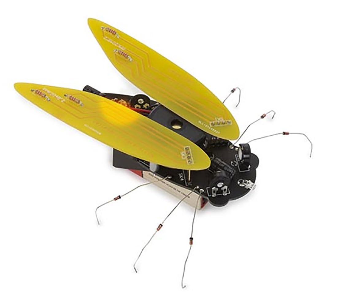
Electronic Cicada Bug Soldering Kit Get ready for Brood-X! Ring in the summer with this beautiful electronic cicada soldering kit. The cicada consists out of three PCBs to mimic the shape of this popular insect as best as possible. The body is matte-black and the two wings are shiny yellow with golden tracks. To finish off the design, you can use the included components to add legs to the cicada bug making it look more realistic. So how does it work? There’s an on-board phototransistor that makes the buzzer sound when it’s dark while an orange LED flickers along. You’ll have everybody fooled! The bug is powered by a 9 V battery (not incl.) which will last about 30 hours when constantly in use. Features –produces the typical cicada sound when dark –buzzer –on/off switch –phototransistor (NPN) –orange LED that flashes to the sound –3 PCBs: (1) black main body, (2) shiny yellow wings Specifications –dimensions: 140 x 110 mm (feet incl.) –power supply: 9 V battery (not incl.) –current consumption: 6.5 mA –battery life: about 30 hours (when constantly in use) –sound level: about 70 dB at 1 meter distance
Package Dimensions : 6.18 x 3.03 x 1.46 inches; 2.82 ounces
Item model number : WSAK204
Date First Available : January 8, 2024
Manufacturer : Velleman
ASIN : B0CRRV7DZ2
Country of Origin : Taiwan
Design Level: Beginner Kit


A. Mark AcetoJanuary 17, 2025
Schematic helps avoid errors with LED and Photo transistor polarities.
For those who appreciate the ethereal beauty of Cicadaâs, and their song, this kit offers a wonderful reminder of their presence. There are two observations I hope will guide everyone to a successful assembly experience. First, the completed project is somewhat fragile and may not be appropriate for the youngest builders or intended recipients. Secondly, even as a lifelong electronics enthusiast and technologist, I found the assembly instructions ambiguous as they pertained to the correct polarity for installation of the photo transistor and LED. While I was able to examine the PC board and make a determination, the schematic diagram provided by the manufacturer removed any doubts. Iâve included it here should anyone find it helpful.
Zachary Thompson.January 17, 2025
So much fun to builddddd!!
This thing is amazing. It didn’t work the first time when I finished it. I went back through and made the connections better and got it to work. I love it